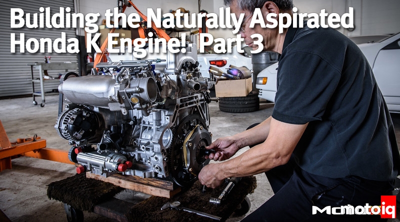

Building the Naturally Aspirated Honda K Engine Part 3, Assembling the Engine
In the previous two installments of our engine build, you were able to take a look at the parts we will be using to build the bottom end and the cylinder head of our Ariel Atom. Notably, we went with a Dailey Engineering dry-sump system, since the Atom has a lot of aero-enhanced grip, and we want to avoid oil starvation.
We also got rid of the horrible K24 Z7 head and are using a much freer flowing K20Z3 cylinder head. It’s CNC ported and prepped by Drag Cartel and stuffed with some of their billet Stage 4 camshafts.
Although we tailored our engine’s parts selection conservatively for reliability, we are hoping to make at least 80 more wheel horsepower than the stock K24 Z7. This is in no way all of what the amazing Honda K motor is capable of doing, but compared to other makes of engines with the same level of modifications, the K will amaze you in the ease that it makes power!
So, we will now put our moderate engine together. There are a few details that we are addressing using the right combination of OEM parts to reach our power and reliability goals. Check it out!


We measured our bores with a bore gauge and our pistons with a micrometer and determined that our bores were fine. We used a fine flex hone to break the glaze on our cylinder walls to help the new rings seat.
Next, we installed the main bearings so we could determine if the bearing clearances were adequate. Note that the interior of the block has been gone over with a die grinder and cartridge rolls to knock off any loose casting sand that could break loose and cause some damage to the engine.

King bearings come in different thicknesses, so we put together some different combinations of bearings to set the final clearance. We do the same thing to the rod bearings as well. Direct measurement with the proper tools is far more accurate than depending on something like plastigage.
Aluminum blocks grow with temperature considerably, so the normal main bearing clearances are very tight compared to old iron blocks. Some modern ones specify less than 0.001″, so you can see how critical this is to maintain oil pressure, control windage, and for long service life.