It all started about around November 2007 when we first received our first 4B11T long block from Japan. I think the EVO X was just released in the US around then so we were definitely one of the first performance and racing companies to have the engine. We quickly tore down the engine for measurement and analysis. From there we started to live and breathe 4B11T product development. Then in February 2008 we received our second 4B11T complete long block assembly with all manifolds, turbos, pumps, accessories, etc. to test on the dyno. Plans for testing and developing the 4B11T on the engine dyno were made around that time also. Tyler and I just got the engine running several weeks ago on the dyno.We'll round up and call it a two year process, but things kept coming on the product development front that prevented us from testing the 4B11T on the dyno. We had visions of grandeur for the 4B11T, but that was well before the world economy decided to took a dive.
It's not a super big deal to get an engine running on one of our dynos, but it isn't a piece of cake either. It's best to model everything in CAD and CNC machine the adapter plate, spline adapter, output shaft and engine mounts. Tyler modeled it all and Lew fabricated most of that stuff with minimal drama. We ended up using a Cosworth XG (ex-IRL engine) output shaft that connects a modified stock flywheel to the dyno's water brake. The bell housing adapter was taken from an old Volvo 5 cylinder World Challenge engine program and was modified to fit the 4B11T. The serpintine belt's idler is from a Cosworth YDX Formula Atlantic engine. It was actually kind of fun making everything work with parts we have around the shop. It added a little spice to the challenge. The engine harness was a separate issue and wasn't very fun. Many of the sensors on the 4B11T are new to the automotive world so finding connectors was a MASSIVE bitch. I could have purchased a factory EVO X engine harness, but I couldn't get myself to buy a $2800 harness, cut off 10 connectors, and throw the rest of it away. So instead I built an engine harness from scratch. We had some of the rare Sumitomo connectors sitting around from past OE projects, but Nate over at Motec saved the day with some of the super rare OE sensor connectors. I discovered that the 4B11T coolant temp sensor connector is the same as a 2002 PZEV Ford Focus and the 4B11T igntion coils are the same as the SR20/RB26 crank angle sensor connector.
The quality of the pics below are terrible. Long story, but I was experimenting with a new camera.

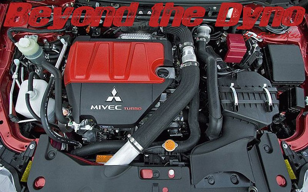
The engine is internally 100% stock with a stock intake manifold, but has a Full-Race twin scroll, twin wastegate exhaust manifold, twin TiAL MVS wastegates, and a Garrett GT35R twin scroll with 1.06a/r turbne housing. For our first stage of testing a stock engine is capable, but we needed to use a no BS turbo with plenty of exhaust flow. The large tube that goes to the roof is connected to the dyno's air conditioning system so the engine can ingest an exact quality of air that we specify. We are able to control barometric pressure, temperature, and humidity of the air. This way test results are repeatable even if tests span over several months regardless of weather conditions. This is what sets our engine dyno testing apart from engine dynos at smaller shops and of course, chassis dynos.

Full Race makes the nicest exhaust manifolds for the tuning market. They are a bit heavy, but are bullet proof and they work awesome. Did you know that the guys there designed their own welding robot that can handle welding bent tubes? Those guys are seriously smart.

Another thing that is great is the data acquisition and logging capabilities of the Cosworth Torrance engine dynos. Here you can see we have 6 EGTs (individual cylinders plus pre and post turbine) and pre and post turbine back pressure. The dyno's control system can view 18 pressure transducers, 16 K-type thermocouples, 16 J-type thermocouples, 16 wideband A/F sensors, and various ECU parameters. For datalogging, we use a Cosworth/Pi Research Sigma logger that has a ton of logging memory and can log at over 8,000Hz. There's so much data that when you export a log to an Excel sheet, Excel pops up a warning dialog box warning that there are not enough columns to display all of the data. Is all of this data necessary? It depends on what you are trying to do, but once you have it, it's hard to live without it. The speed at which you can acquire and review data truly aids in engine development, component testing, and validation.

A Pectel SQ6 ECU controls the engine. The configurable FPGA allows the SQ6 to read virtually any kind of cam and crank trigger signal with absolute precision up to 16,000rpm. Yes, that's 16,000rpm! Variable cams, drive by wire throttle, wastegate control, knock control, wideband NTK UEGO Lambda (x2) are all built in to one compact and lightweight unit. There are plenty of other features available such as traction control, transmission control with throttle control (downshift throttle blip), up to 12 peak and hold sequential injector drivers, up to 8 sequential ignition coil drivers (CDI is built in already too so no external CDI unit is necessary), up to 8 digital outputs, up to 14 pwm outputs, up to 18 analog inputs (who needs a logging dash?) stepper motor control, and DC motor controls (x2) and many other features are built in too, but not all of these features are applicable on an engine dyno of course. ECU communications is handled by serial, CAN, or Ethernet for the ultimate in speed. When you consider all of the features the ECPro/SQ6 offers, it really isn't that expensive. The ECPro is toned down a bit for “plug and perform” applications, but it is also a bit more affordable. The more I use the Cosworth ECPro and Pectel SQ6 series of ECUs, the more I wonder how I lived life without them for so long. I want to put an ECPro or SQ6 on every modified car I own.
Anyhow for this Stage 1 round of testing, Tyler and I will be doing some camshaft performance validation (yes, bigger cams are coming for those of you with bigger balls) and a series of intake manifold tests. You can design, model, simulate, flow, analyze any component on a computer, but none of it means much of anything unless it is verified and validated in the physical world.
After this engine we will bounce back to the Cosworth 2.6L stroker Subaru EJ257B for stage 2 of camshaft performance validation and some other cool stuff. Unfortunately I cannot discuss publicly, but it's exciting stuff. Then we're back to stage 2 of the 4B11T in stroked big horsepower Cosworth 2.2L form for some even bigger cam validation. Now that is going to be fun.
Somewhere with all of this going on, I need to get my RB26 on there somehow. Tyler wants to develop a K20A on there too. If only there were more time in a day…